Calculating rod deflection under static load

This board is for discussing the repair and restoration of bamboo fly rods, makers discussion and construction techniques relating to same. Examples would be different techniques or methods used by restorationists and makers.

Moderator: Titelines

User avatar
henkverhaar
Bamboo Fanatic
Posts: 1260
Joined: 07/02/16 15:37
Location: Near the Geul...

Calculating rod deflection under static load

#1

Post by henkverhaar »

Who knows, some of you may enjoy this. I know I did:

https://digitalcommons.library.umaine.e ... ext=honors

I've taken the Matlab scripts and functions from the appendix to use, initially, as a tool to compare theoretical rod deflection under load for different tapers - here a Powell taper ('Test Taper') vs. my own default taper ('Geul', a 7'6" #4 taper).

Image

User avatar
AlexX!!
Sport
Posts: 82
Joined: 03/31/17 06:22
Location: Germany
Contact:

Re: Calculating rod deflection under static load

#2

Post by AlexX!! »

Nice.. thanks for the share,

i once made a FEM simmulation via CatiaV5 https://www.instagram.com/p/BaHW4iClEdP
but find it way to complicated, convenient would be the defl. simmulation directly in the taper Xls sheet

cheers
Alex

User avatar
Fcs
Guide
Posts: 240
Joined: 05/31/15 10:15
Location: Bellingham WA
Contact:

Re: Calculating rod deflection under static load

#3

Post by Fcs »

+1 on thanks for share.

I'm always on the lookout for work to compare my (oversimplified) deflection calculations to.
"Wherever the fish are, that's where we go."
Richard Wagner

User avatar
henkverhaar
Bamboo Fanatic
Posts: 1260
Joined: 07/02/16 15:37
Location: Near the Geul...

Re: Calculating rod deflection under static load

#4

Post by henkverhaar »

FWIW, I've taken the deflection function and cobbled up a script that uses that deflection function to determine locations for the guides (my original aim was to show that even for different tapers, optimized guide locations, for a given number of guides, do not vary much at all, and coincide pretty well with locations given by the standard empirical formulas; which indeed appears to be the case). Here's the script, for those who can run either MATLAB or Octave, or are willing to recode into another environment. And I'm always open to comments, improvements or notifications of actual mistakes/errors/goofs/whatever ;-)

Code: Select all

E = 6e6; %default Modulus of Elasticity for bamboo
p = 0.2; %load on tip (0.2 lbs for a nice bend under load, to provide a good guide distribution under load
n = 500; %number of segments
q = 9;   %number of guides plus 1

Guides = zeros(1,q-1);
Loc = zeros(1,q-1);
Dist = zeros(1,q-1);

%Stations in inches - standard spacing for 'normal' planing forms is 5 inch
X = [0:5:90]';
%Rod dimensions at each station, starting at tip, in mm - for stress calculations, these are converted to inches. If specified in inches, no need to divide by 25.4...
Y = sort([1.66 2.06 2.48 2.92 3.36 3.82 4.32 4.86 5.36 5.7 5.86 5.98 6.18 6.52 7.12 7.9 8.56 8.56 8.56]'/25.4,'descend');
Taper = [X Y]; % taper of 7'6" #4 Geul


%RUNS taper_defl TO CREATE DEFLECTION VECTORS FOR default and test taper;
%this requires the (slightly altered) taper_defl function from Scully - The Effect of Material Variability on the Deflection of Bamboo Fly Rods: https://digitalcommons.library.umaine.edu/cgi/viewcontent.cgi?article=1462&context=honors

[X1,Y1,Xo,Yo,Yf1,Xf1] = taper_defl(p,n,E,Taper);

%PLOT
figure(1);
plot(Xo,Yo,X1,Y1,'k','LineWidth',2);
grid on;
%LABELS
title('Guides','fontsize',24); xlabel('Length (inches)','fontsize',18); ylabel('Vertical Deflection (inches)','fontsize',18);
axis equal;
%set(figure(1));
lgd = legend('Unloaded Rod','Loaded Rod'); lgd.FontSize = 12;
%This bounds the graph to the length of the unloaded rod (x-dimension) and the  deflection of the loaded rod (y-dimension) axis ([0 Xf1 -Yf1 5]);
%This divides the vertical plane into equally spaced slices to determine the location of the guides
ticks = (-Yf1:Yf1/q:0);
yticks(ticks);

%Determine the crossing points of the rod under load with the 'ticks', and sets the equivalent point (x-coordinate) on the unloaded rod as the location of a guide
for i=2:q
    I = find(Y1<ticks(i),1);
    Xo(I);
    Guides(i-1) = Xo(I);
end

%Convert guide locations to distance from tip in cm
Loc = round (2.54 *(X(end) - Guides),1)
%Provide inter-guide distances as well as locations from tip
Dist(1) = Loc (1);
for i=2:q-1
    Dist(i) = Loc(i)-Loc(i-1);
end
Dist
% find(Y1<-16.37,1)
% Xo(482)

perfesser
Guide
Posts: 306
Joined: 06/30/19 20:52
Location: south carolina

Re: Calculating rod deflection under static load

#5

Post by perfesser »

.
Last edited by perfesser on 07/01/20 16:12, edited 1 time in total.

User avatar
Mike McGuire
Master Guide
Posts: 702
Joined: 03/16/10 19:00

Re: Calculating rod deflection under static load

#6

Post by Mike McGuire »

This is an interesting and useful contribution. The one thing left undone was to hang a weight on a real rod and compare its deflection to his calculated deflections. The calculation method is similar to one used by Falke Gregersen. He described it in a blog "Mathematics and Fly Fishing." Unfortunately blog has disappeared and I haven't been able to turn it up with archives like the Wayback Machine. I'm not sure if Gregersen is around anymore. I did make hard copy prints of some of the articles. I also did set up a spreadsheet calculation of deflection--it was quite sensitive to the value of modulus I used. As Scully's article shows, it's rather variable.

Mike
A Selection of my DIY Rodmaking Tools

User avatar
henkverhaar
Bamboo Fanatic
Posts: 1260
Joined: 07/02/16 15:37
Location: Near the Geul...

Re: Calculating rod deflection under static load

#7

Post by henkverhaar »

Yep, However, actual absolute deflection wasn't my first aim - that was relative deflection / taper comparison, and trying to make a point concerning guide placement (more specifically, that it is not nearly as critical as some people will have you believe, and that 'tweaking' the placement to conform to the bending of a specific taper is rarely necessary - the default guide placement formulas will provide a very useful approximation of optimal placement).

Interesting thing is that if you take the second derivative of the displacement curve (numerical, of course), you get a 'stress' curve for the rod under load, unlike the standard Garrison stress curve for an (essentially) unloaded rod. In fact if you apply different loads in the calculation, you can see the change in stress curve under increasing load...

I seem to remember that there was a paper where the authors DID compare calculations with actual empirical deflection - will try and find it...

BTW, are you aware that there is a scanned copy of Don Phillips 'The technology of fly rods' floating around on the interweb somewhere?


Here's something: Bending of a Tapered Rod: Modern Application and Experimental Test of Elastica Theory, M. P. Silverman, Joseph Farrah; different approach to calculation, but based on fundamentally the same theory. With actual measurements on 5 fishing rods.
Fishing Rod Guide Placement; A Major Qualifying Project Submitted to the faculty of Worcester Polytechnic Institute
In partial fulfillment of the requirements for the Degree of Bachelor of Science, Erica Parker, Shawn Popieski also present actual measurements and simulations.

User avatar
Fcs
Guide
Posts: 240
Joined: 05/31/15 10:15
Location: Bellingham WA
Contact:

Re: Calculating rod deflection under static load

#8

Post by Fcs »

I performed a quick check for the tip deflection on a Garrison taper rod with a 2.00 ounce weight suspended from the tip. The total deflection at the tip was 19.75 inches. Scully's math gives this deflection with the MOE set to 4.7mpsi, which is plausible. I did not check the deflection along the rod vs. the model.

Of course the elephant in the room is the variability of the raw material (between culms, along the culm and around the culm), and can we find a practical way to measure it before we use it. That is the main point of Scully's thesis.

I don't have Matlab on my current computer so I translated it to another language, making a couple minor changes. Its interesting that the number of iterations to converge varies greatly between tapers and weights. Something to dig into.
"Wherever the fish are, that's where we go."
Richard Wagner

User avatar
cdmoore
Bamboo Fanatic
Posts: 3753
Joined: 03/23/04 19:00

Re: Calculating rod deflection under static load

#9

Post by cdmoore »

I might be wrong, but isn't that similar to what Wayne Maca does with his sound frequency testing? I believe he's looking for variations in density, perhaps around the culm, but more likely along it's length, and based on the idea that sound travels at different rates through different densities. Don't know at what production stage he does this (pre-split, post-split, before heating, etc.) or if it is worthwhile for a maker who doesn't work with strips that are standard width and thickness prior to processing. Also not sure if he was looking merely for aberrations or if he correlated test results to MOE; I don't think he did the latter. I believe he borrowed this raw material intake testing methodology from the snowboard industry. I read the old patent but don't recall for sure. Maybe someone with firsthand knowledge can chime in.

I've been reading up on wood fiber creep lately and was interested to learn about wet/dry cycling as a strong contributing factor. It reminded me of how soft wet cane can be during the cane storage and rod making process. Glad to see this factor acknowledged in the Scully paper. MOE is probably a dynamic variable, definitely according to season but probably within a day's fishing as well.

Following this thread with interest...

Thanks, Hank.

User avatar
Mike McGuire
Master Guide
Posts: 702
Joined: 03/16/10 19:00

Re: Calculating rod deflection under static load

#10

Post by Mike McGuire »

henkverhaar wrote: ...
Interesting thing is that if you take the second derivative of the displacement curve (numerical, of course), you get a 'stress' curve for the rod under load, unlike the standard Garrison stress curve for an (essentially) unloaded rod. In fact if you apply different loads in the calculation, you can see the change in stress curve under increasing load...

I seem to remember that there was a paper where the authors DID compare calculations with actual empirical deflection - will try and find it...

BTW, are you aware that there is a scanned copy of Don Phillips 'The technology of fly rods' floating around on the interweb somewhere?
...
Maybe it would be possible to go from the stress curve of a bent rod to a new taper for a different loading condition a la Garrrison/Hexrod/RodDNA by some sort of iterative process...

There was an article in Power Fibers 56, July 2014, "Deflection and Stress Analysis of a Bamboo Fly Rod" by Bryan Coles. He did calculate and compare to a real rod.

I was lucky enough to get the Phillips book when it was first published. There is a lot of good stuff in it, the basics one would need to know to do it, but not much on how to actually calculate the bend in a rod.

Mike
A Selection of my DIY Rodmaking Tools

BryanColes
Member
Posts: 2
Joined: 12/31/19 18:12

Re: Calculating rod deflection under static load

#11

Post by BryanColes »

Since Mike McGuire mentioned an article I wrote several years ago for Todd Talsma I'll jump in with a comment re comparing calculated and measured deflections in a fly rod.

In 2012 I started using using a Freeware Finite Element Analysis (FEA) tool to analyze the flyrods I was building. My objective was to develop a tool that would constitute an improvement over the 'slide rule' model that had been developed by Everett Garrison. Being a mechanical engineer I have a tremendous regard for the contribution that Garrison made to our craft but I also understand the limitations of his model and hoped to develop a more advanced analytic technique that could provide us with a better understanding of our designs.

In 2014 I worked with Todd to publish the article that Mike McGuire references which compared calculated deflection data to measured data for a specific rod that I was building. That comparison showed good agreement between the calculated and measured data for the tip and butt sections but there was a measurable difference in the mid area. After the article was published I continued to dibble and dabble with the model trying to identify the source of the difference, and I finally found it. The published data incorporated the assumption that the rod was a 'cantilevered beam' which meant that butt end of the rod was assumed to be firmly constrained in the horizontal. In reality, when the rod deflection data were measured the rod was constrained at two isolated points that placed a downward force at the far butt end of the rod and an upward force at a point that was 3.5 inches into the rod (measured from the butt end toward the tip). When I replaced the initial cantilever assumption with this new, more accurate, boundary condition and re-ran the model the deflection discrepancy disappeared and the calculated data agreed with the measured data over the full and entire length of the rod (at least to within 1/16 inch which was my measurement resolution).

I calculated rod deflections for various tip loads and found that the calculated deflection data agreed with measured data very well over a wide range of tip loads. Once the load conditions and deflection are known it is a straightforward task to accurately calculate stress.

I should point out that in my personal opinion stress calculations are pretty much meaningless. Deflection is the important parameter. The reason I believe this is that the role of a fly rod is to transfer energy from the hand of the caster to the fly line. The caster puts energy into the rod by moving it and the rod transmits this energy to the fly line (which drags the fly through the air and onto the water). Energy is therefore the key factor in the whole process and calculating stress is only useful if you want to make sure your rod won't break when it is loaded.

The energy stored in a specific location within the fly rod is proportional to deformation (deflection) of the rod at that location. Therefore, the energy distribution within a 'bent' rod can be determined via the deflection analysis.
I'm guessing that the manner in which energy is released from the rod and transferred to the fly line is rather intimately related to the manner in which the energy is stored in the rod during the casting process. If you drive the spring at the right, rate energy will be transferred smoothly and efficiently. If you drive the spring at the wrong rate, energy will not be transferred well and you'll end up with the well known 'pile of line' at your feet. So we want to design springs (rods) that are well matched to our hand (the driving force) and the load (the fly line). This is why I've always believed that Max Satoh was on the right track with DynaRod.

One last comment - the current 'guide spacing' discussion has re-ignited a task that I had in mind years ago to measure the deflection curve of a rod in two different conditions; 1) with a load applied directly to the tip (no guides), and 2) with the same load applied to a line threaded through the guides. Has anyone ever made this comparison?

User avatar
Fcs
Guide
Posts: 240
Joined: 05/31/15 10:15
Location: Bellingham WA
Contact:

Re: Calculating rod deflection under static load

#12

Post by Fcs »

Bryan, thanks for your detailed post. I’m not an engineer and I know very little about FEA, so tell me if this is not a valid question. What did you use for the MOE of bamboo? Was it a fixed value or did it decline with increasing rod dimension (or maybe its with the location of the element in the rod)?
"Wherever the fish are, that's where we go."
Richard Wagner

BryanColes
Member
Posts: 2
Joined: 12/31/19 18:12

Re: Calculating rod deflection under static load

#13

Post by BryanColes »

I used the MoE value reported by Bob Milward. I also ran the FEA model several times with different values as a quick sensitivity test. The calculated deflection numbers changed when the MoE was changed, just as one would expect. But in the end, I believe my calcs pretty much confirmed Bob's MoE data because my calculated deflections match measured deflections over a range of tip loads (from 0 to 3 oz) and rod geometries.

I've been playing with a design for a 8'6" 4wt 3pc rod with integral bamboo ferrules, both hollow and solid. FEA can model the structural geometry in as much detail as one would want to go to the trouble of specifying so I've specified the hollow vs solid configurations as well as various ferrule geometries. The hollow vs solid geometries show slightly different deflection curves but they are surprisingly similar. Variations in ferrule geometry have shown very little effect on deflection curves. In my 'field trials' I find that both rods 'throw the line' similarly but I prefer the hollow configuration because of the lower weight. I don't think my casting ability is good enough or sensitive enough to evaluate differences in rod dynamics.

As I mentioned in my previous post, the boundary conditions (how the butt end was supported during the actual deflection measurement tests) were really important. My calcs certainly showed that the cantilever assumption, which is so common, is NOT a good assumption. I guess I should not have been surprised by this, but I was.

The real limitation of the FEA approach is that it is a static model - time is not a variable. And I am a strong proponent of the idea that a fly rod is a very dynamic tool. With that said, the user's casting style (the forcing function) and the operating conditions (line length, wind/no wind, etc) are so variable that it's hard for me to see how a truly 'optimized' design could ever be developed. 'Fast' rods vs 'slow' rods could certainly be designed but I think this can be accomplished, to a significant degree, with static deflection analyses (sort of like what Orvis does with their Full-Flex/Mid-Flex/Tip-Flex ratings). I'm finding that this approach, combined with 'field testing', is resulting in some rods that I like.

I'm looking at DynaRod again but, unfortunately, Max never explained his approach to dynamic analysis in much detail. Another limitation with DynaRod is that, as far as I know, Max doesn't take aerodynamic loads into account and I think that any rod analysis tool would need to take this factor into account in order to be considered really 'complete'. So we still have along way to go.

Bryan.W.Coles@gmail.com

User avatar
Fcs
Guide
Posts: 240
Joined: 05/31/15 10:15
Location: Bellingham WA
Contact:

Re: Calculating rod deflection under static load

#14

Post by Fcs »

This is a report on what I learned working with the Scully algorithm for static deflection of a bamboo rod.

I've been dabbling off and on with deflection calculations for a couple years. I have zero mechanical engineering background. I came up with a few solutions that seemed reasonable but I never had any confidence in their correctness or robustness. They were similar to Scully's method, in that they used an iterative approach, small deflection theory and accumulating the deflection over short segments. But they were not sound. So I was interested in the simple algorithm Scully developed.

Problem 1. Implementation

I recoded the algorithm in Perl, my language of choice for quick and dirty. I discovered that the algorithm did not always converge. It would tend to oscillate between two extremes. Some particular tapers were problems, as were higher values of the force (weight) input. (I do not know if Scully had this problem or if MATLAB has some magic. Or maybe he chose his tapers and small forces carefully.) A little addition which automatically reduced the size of the oscillations solved that problem (details upon request). The algorithm does seem to break down for very large deflections (over 50% of rod length).

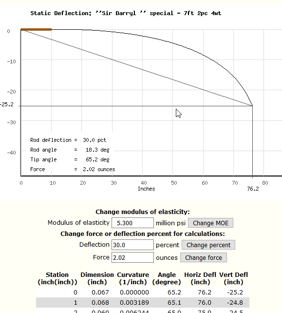
After some testing I decided to add it to my Hexrod program. The default assumes a MOE of 5.3 million PSI and deflects to 30 percent of the total rod length. The user can change the MOE and either the total deflection to solve for force or vice versa. Segment length is 0.2 inches, which is smaller than necessary, but execution time is only a fraction of a second. Output is a graph and a table. Like this:

Image

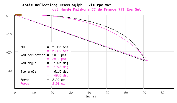
Most deflection curves look pretty much alike; someone will need to use the tables for any sort of analysis. The Compare action in Hexrod gives two curves on a graph. Here are two 7.5 ft 5wt rods a (fast) Cross and a slow(Hardy):

Image

The Hexrod program works for hex, quad or penta configurations, solid or hollow builds, and American or metric units. No doubt I will make some tweaks in the coming weeks. Someday I will work with Scully's code for large deflection. I have another working code for large deflection of an untapered beam that has a more detailed derivation, for comparison.

Problem 2: Dynamic Deflection

It turned out to be simple to adapt the algorithm to a somewhat dynamic deflection analysis. Here is the line in Scully's MATLAB code that computes the curvature:

Code: Select all

curv(i) = p* (X(n) - X(i)) / EI(i)
The numerator term is the moment. We simply substitute a dynamic moment such as

Code: Select all

curv(i) = (Sum from j=i+1 to n)(G * W(j) * (X(j) - X(i)) / EI(i)
W(j) is the total weight of the cast components for section j (bamboo+ferrule+varnish&guides+line in guides) and W(n) includes the weight of the line being cast. G is an force multiplier. These are all items included in Garrison's stress calculation, with G=4. I admit I borrowed this logic from Max's DynaRod.

Here is the dynamic deflection for the SirD taper casting 40 feet of DT4:

Image

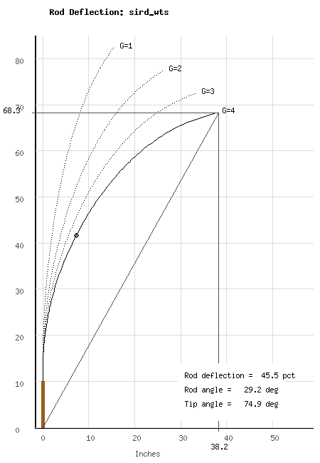
I will have to work with this for while before I release it for the unwashed masses of Hexrod users.

Problem 3: Curvature/Stress calculations

Scully's algorithm returns four vectors for n-1 segments: the deflection coordinates X and Y, the slope of the segments, and the curvature. The first three are intuitive, but the curvature looked interesting. (You can also calculate it yourself from the deflections.) I made a plot:

Image

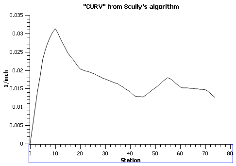
Even a blind pig finds the occasional acorn! That is the SirD stress curve, with a different vertical scale:

Image

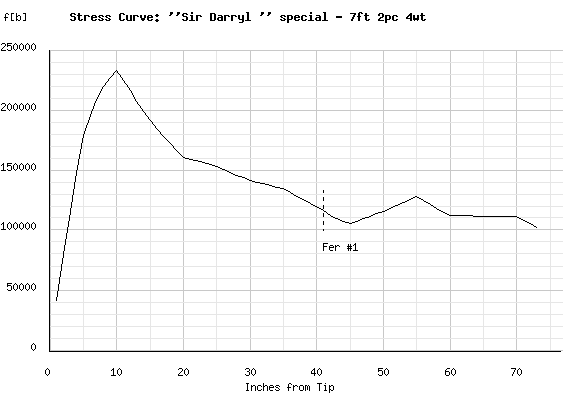
I guess I should have known this was coming; Scully says the curvature is the second derivative of deflection, and Henk mentioned that stress is the (a) derivative. I haven't worked out the scaling of the vertical axis; I assume it involves multiplying the curvature by the MOE in ounces per square inch. I will need to dig into this, unless some engineer wants to give me a hint.

What does this mean for application of deflection to rod design? First, if you have a deflection curve, you can calculate curvature and, with some assumptions about line weight, the taper. If you modify the curvature (say by stretching) and derive a new rod you are just modifying (stretching) the stress curve. This has been available in Hexrod for 20+ years. Second, is there really any advantage to working with deflection over stresses? For years people have been telling me that stress calculations are a lot of hooey and real taper design must be done with deflection. They are the same. Even if you add more factors to your deflection, you can probably add them to stress calculations.

I know this stuff is pretty elementary, and is nowhere near as complete as FEA, but I'm having a helluva good time playing with it.
--
Frank Stetzer
"Wherever the fish are, that's where we go."
Richard Wagner

User avatar
dkrismer
Member
Posts: 8
Joined: 01/18/15 02:53
Location: Snohomish, WA

Re: Calculating rod deflection under static load

#15

Post by dkrismer »

Frank, this is good stuff! I am really interested in using rod deflection characteristics for designing bamboo fly rods. This makes sense to me as the intent is to use the rod as a cantilevered spring to transfer stored energy from the rod (spring) into kinetic energy in the fly line (velocity). I am at the starting point of my thoughts on this and have been reading up on the various papers and approaches for computing rod dynamics, deflection, energy, tip speed, etc. One idea (could be stupid) that I want to see if I can pull off is to take my favorite carbon fiber rod (my old trusty Loomis GL3) and replicate the deflection, stiffness, and dynamics in a new custom bamboo taper. Or is this too much apples and oranges?

Dave Krismer
Snohomish, WA

User avatar
Fcs
Guide
Posts: 240
Joined: 05/31/15 10:15
Location: Bellingham WA
Contact:

Re: Calculating rod deflection under static load

#16

Post by Fcs »

Dave,

I suppose it is possible to design a cane rod with the same deflection as a graphite rod, but I'm sure it wouldn't cast the same. It might also be too heavy to use, even if hollowed. Maybe someone will have a more scientific response.

I too have a favorite old Loomis, an IM6 I built from a blank in 1986.
--
Frank Stetzer
Bellingham WA
"Wherever the fish are, that's where we go."
Richard Wagner

User avatar
DA
Guide
Posts: 222
Joined: 07/01/10 18:00

Re: Calculating rod deflection under static load

#17

Post by DA »


User avatar
Fcs
Guide
Posts: 240
Joined: 05/31/15 10:15
Location: Bellingham WA
Contact:

Re: Calculating rod deflection under static load

#18

Post by Fcs »

Thanks DA. I saw this some years ago but had forgotten about it. It will be helpful.
"Wherever the fish are, that's where we go."
Richard Wagner

User avatar
henkverhaar
Bamboo Fanatic
Posts: 1260
Joined: 07/02/16 15:37
Location: Near the Geul...

Re: Calculating rod deflection under static load

#19

Post by henkverhaar »

Frank - very interesting! ;-)
Fcs wrote:This is a report on what I learned working with the Scully algorithm for static deflection of a bamboo rod.

Problem 1. Implementation

I recoded the algorithm in Perl, my language of choice for quick and dirty. I discovered that the algorithm did not always converge.
My finding too. It works, roughly, until a deflection of 1/3 of rod length. Which worked for me, as my -original- intent was to find an algorithm to calculate guide distribution based on deflection...
Problem 2: Dynamic Deflection

It turned out to be simple to adapt the algorithm to a somewhat dynamic deflection analysis. Here is the line in Scully's MATLAB code that computes the curvature:

Code: Select all

curv(i) = p* (X(n) - X(i)) / EI(i)
The numerator term is the moment. We simply substitute a dynamic moment such as

Code: Select all

curv(i) = (Sum from j=i+1 to n)(G * W(j) * (X(j) - X(i)) / EI(i)
Gotta try that - but what I think I understood from what little information Max Satoh provides (or that I could find), he seems to suggest that dynamic deflection is based on the harmonics of the fly rod, more specifically the second harmonic. I'm not sure I fully agree, but I think I see his point - where casting does in fact put a 'forward' moment on the 'handle' and a 'backward' moment on the tip - from the inertia of the line. I've been hunting the web for algorithms to determine 'tapered cantilever beam' harmonics/eigenvalues/whathaveyou, but so far haven't been able to come up with something that I could easily copy or code into MATLAB. Still looking though...
Problem 3: Curvature/Stress calculations
Yes, stress and deflection - at least within this formalism, are 'interchangeable' and therefore taper, deflection, curvature, and stress calculations all define the same basic design, and there is no intrinsic advantage of deflection over stress, or the other way around. As stated, my only reason to want to be able to calculate deflection was to use that deflection to calculate guide placement (to show that the belief, held by some, that individual blank guide placement, possibly augmented by test casting and optimising the guide placement during that casting, is superior to using a default algorithm, is in fact hogwash; I don't have a full analysis, but my experience leads me to believe that indeed default guide placement approaches are as good a solution as 'individual blank test deflection guide placement' approaches...)

Cheers

Henk

User avatar
Mike McGuire
Master Guide
Posts: 702
Joined: 03/16/10 19:00

Re: Calculating rod deflection under static load

#20

Post by Mike McGuire »

Frank
A couple of questions to understand better what you have done. Is the stress curve you show just the classic rigid rod Garrison stress curve calculated with G = 4? Then should I understand that the "Curvature" curve is calculated by the Scully method with G = 4. If this so, then according to the Wikipedia article on Euler-Bernoulli beam theory in particular this section, the scale factor that takes curvature to stress is just the MOE times the distance from the neutral axis of the beam to the surface, so this scale factor will vary with the cross section dimension of the rod.

Mike
A Selection of my DIY Rodmaking Tools

Post Reply

Return to “Rod making, restoration, repairs and discussion on those related topics concerning bamboo rods.”